The configuration settings for the Ultrasonic Sensor View to be provided by the environment simulation. More...
Public Attributes | |
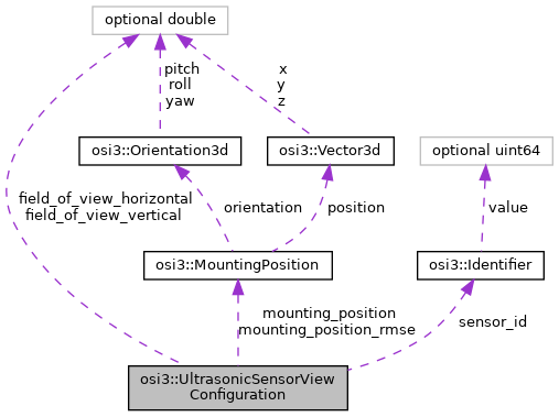
| optional Identifier | sensor_id = 1 |
| optional MountingPosition | mounting_position = 2 |
| optional MountingPosition | mounting_position_rmse = 3 |
| optional double | field_of_view_horizontal = 4 |
| optional double | field_of_view_vertical = 5 |
Detailed Description
The configuration settings for the Ultrasonic Sensor View to be provided by the environment simulation.
Member Data Documentation
◆ field_of_view_horizontal
| optional double osi3::UltrasonicSensorViewConfiguration::field_of_view_horizontal = 4 |
Field of View in horizontal orientation of the physical sensor.
Viewing range: [- field_of_view_horizontal/2, field_of_view_horizontal/2] azimuth in the sensor frame as defined in Spherical3d.
Unit: rad
◆ field_of_view_vertical
| optional double osi3::UltrasonicSensorViewConfiguration::field_of_view_vertical = 5 |
Field of View in vertical orientation of the physical sensor.
Viewing range: [- field_of_view_vertical/2, field_of_view_vertical/2] elevation in the sensor frame at zero azimuth as defined in Spherical3d.
Unit: rad
◆ mounting_position
| optional MountingPosition osi3::UltrasonicSensorViewConfiguration::mounting_position = 2 |
The physical mounting position of the sensor (origin and orientation of the sensor coordinate system) given in vehicle coordinates [1]. The physical position pertains to this detector individually, and governs the sensor-relative coordinates in features detected by this detector.
- x-direction of sensor coordinate system: sensor viewing direction
- z-direction of sensor coordinate system: sensor (up)
- y-direction of sensor coordinate system: perpendicular to x and z right hand system
- Reference:
- [1] DIN Deutsches Institut fuer Normung e. V. (2013). DIN ISO 8855 Strassenfahrzeuge - Fahrzeugdynamik und Fahrverhalten - Begriffe. (DIN ISO 8855:2013-11). Berlin, Germany.
- Note
- The origin of vehicle's coordinate system in world frame is (
MovingObject::base.BaseMoving::position+ Inverse_Rotation_yaw_pitch_roll(MovingObject::base.BaseMoving::orientation) *MovingObject::VehicleAttributes::bbcenter_to_rear) . The orientation of the vehicle's coordinate system is equal to the orientation of the vehicle's bounding boxMovingObject::base.BaseMoving::orientation. - A default position can be provided by the sensor model (e.g. to indicate the position the model was validated for), but this is optional; the environment simulation must provide a valid mounting position (based on the vehicle configuration) when setting the view configuration.
◆ mounting_position_rmse
| optional MountingPosition osi3::UltrasonicSensorViewConfiguration::mounting_position_rmse = 3 |
The root mean squared error of the mounting position.
◆ sensor_id
| optional Identifier osi3::UltrasonicSensorViewConfiguration::sensor_id = 1 |
The ID of the sensor at host vehicle's mounting_position.
This is the ID of the physical sensor, to be used in its detected features output; it is distinct from the ID of its virtual sensor.
The ID is to be provided by the environment simulation, the sensor model is not in a position to provide a useful default value.
The documentation for this struct was generated from the following file:
- osi_sensorviewconfiguration.proto